- 中文网站请点击 http://www.pinxinggroup.com
-
 +86-21-57566731
-
 cai@pinxingmotor.com
-
 DOWNLOAD

 English
 русский
 Français
 عربى
عربىCauses, hazards, and solutions for generator shaft voltage
With the increasing capacity of single generator units, shaft voltage has become a serious problem for large generators adopting static self-excitation systems. The waveform of shaft voltage contains complex harmonic pulse components, which are particularly detrimental to oil film insulation. When the shaft voltage does not exceed the oil film's breakdown voltage, the shaft current is very small. If the shaft voltage exceeds the bearing oil layer breakdown voltage, a large shaft current will be generated in the bearing, the so-called EDM current, which will burn bearing components and cause significant damage. Magnetic circuit asymmetry, unipolar effect, capacitive current, electrostatic effect, static excitation system, permanent magnetization of the casing, shaft, etc., can all potentially cause shaft voltage.
Shaft voltage refers to the voltage generated between the two bearing ends of a motor or between the motor shaft and the bearing during motor operation. Under normal circumstances, when the shaft voltage is low, the lubricating oil film between the generator shaft and the bearing provides good insulation. However, if the shaft voltage rises to a certain value for some reason, it will break down the oil film and discharge, forming a circuit for shaft current generation. Shaft current not only disrupts the stability of the oil film, causing the lubricating oil to gradually deteriorate, but also, because the shaft current passes through the metal contact point between the bearing and the shaft—a very small contact point with a high current density—it generates extremely high temperatures instantaneously, causing localized melting of the bearing. The melted bearing alloy, under the pressure of rolling, splashes and burns small pits on the inner surface of the bearing. Ultimately, the bearing will break due to accelerated mechanical wear, and in severe cases, the bearing shell will burn out, causing an accident and forcing a shutdown.
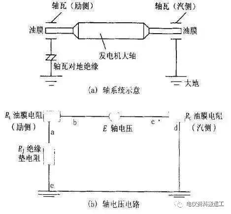
Generator shaft voltage is always present, but it is generally not high, usually ranging from a few volts to a dozen volts. However, when the insulating pads fail due to oil stains, damage, or aging, the shaft voltage is sufficient to break down the oil film between the shaft and the bearing, causing a discharge. Over time, this will gradually deteriorate the quality of the lubricating and cooling oil, and in severe cases, it will burn out the shaft and bearings, resulting in a shutdown accident.
1. Causes of Generator Shaft Voltage
(1) Shaft Voltage Caused by Magnetic Asymmetry
It is an AC voltage existing at both ends of the turbine generator shaft. Due to the use of sector-shaped stamped laminations in the stator core, the different eccentricities of the rotor, the different permeability of the sector-shaped laminations, and the shaft guide grooves used for cooling and clamping, etc., magnetic asymmetry is caused by the generator manufacturing and operation, resulting in an alternating magnetic flux loop including the shaft, bearings, and foundation plate. This generates a voltage difference at both ends of the generator shaft. Each type of magnetic asymmetry will cause a shaft voltage component with corresponding amplitude and frequency. The various shaft voltage components are superimposed, making the frequency composition of this shaft voltage very complex. The fundamental component has the largest amplitude, the 3rd and 5th harmonics have slightly smaller amplitudes, and the higher harmonic components have very small amplitudes. This AC shaft voltage is generally 1~10V, and it has a large amount of energy. If no effective measures are taken, this shaft voltage will form a loop through the shaft-bearing-foundation plate, etc., generating a large shaft current. The electric arc caused by shaft current is applied between the bearing and the shaft surface. Its main consequence is wear on the tungsten carbide in the bearing and on the shaft surface, and rapid deterioration of the lubricating oil. This accelerates the mechanical wear of the bearing, and in severe cases, can cause the bearing shell to burn out.
(2) Shaft voltage caused by electrostatic charge
This DC voltage, appearing between the shaft and the grounding plate, is generated by the electrostatic charge produced by the friction between the high-speed flowing wet steam and the turbine low-pressure cylinder blades under certain conditions. This electrostatic effect only occurs occasionally under certain steam conditions and is not frequent. Depending on the operating conditions, this type of shaft voltage can sometimes be very high, reaching hundreds of volts, causing a tingling sensation when touched. It is not easily conducted to the exciter side, but if no measures are taken to conduct this electrostatic charge to the ground, it will accumulate on the bearing oil film on the turbine side of the generator and eventually discharge on the oil film, leading to bearing damage.
(3) Shaft voltage caused by static excitation system
Currently, large steam turbine generator sets generally use a static excitation system. Due to the influence of thyristor arc commutation, a new shaft voltage source is introduced into the static excitation system. The static excitation system supplies DC voltage to the generator excitation winding through a static thyristor rectifier, and this DC voltage is a pulsating voltage. For a static excitation system using a three-phase fully controlled bridge, the waveform of its excitation output voltage has 6 pulses within one cycle. This rapidly changing pulsating voltage generates an AC voltage between the shaft and ground through capacitive coupling between the generator excitation winding and the rotor body. This shaft voltage is pulsating and spike-shaped, with a frequency of 300Hz (when the AC voltage frequency of the excitation system is 50Hz). It is superimposed on the shaft voltage caused by magnetic asymmetry, thus causing the oil film to withstand a higher spike voltage. When it increases to a certain extent, it breaks down the oil film, forming a current that causes burning and damage to mechanical parts.
(4) Shaft voltage caused by residual magnetism
When the generator is severely short-circuited or under other abnormal operating conditions, the main shaft, bearings, casing, and other components are often magnetized and retain a certain amount of residual magnetism. Magnetic lines generate longitudinal branches at the bearings, and when the main shaft of the unit rotates, an electromotive force is generated, called a unipolar electromotive force. Under normal circumstances, the unipolar potential generated by weak residual magnetism is only in the millivolt range. However, when there is a short circuit between rotor winding turns or two-point grounding, the unipolar potential will reach several volts to tens of volts, generating a large shaft current. This current flows axially through the shaft, bearings, and foundation plate, not only burning out the main shaft and bearing bushes but also severely magnetizing these components, making unit maintenance difficult.
2. Hazards Caused by Generator Shaft Voltage The magnitude of shaft voltage varies depending on the specific unit. Generally, the larger the unit capacity, the greater the asymmetry in its air gap flux and structure. The greater the harmonic components in the magnetic field, the higher the core saturation, and the greater the stator unevenness, the higher the peak shaft voltage. The shaft voltage waveform has complex harmonic components. Units using static controllable rectifier excitation have a high pulse component in their shaft voltage waveform, which is particularly harmful to oil film insulation. When the shaft voltage reaches a certain value, if appropriate measures are not taken, the oil film will break down, generating shaft current.
If the shaft current of a steam turbine generator set is very high, the journals, bearings, and other related components through which the shaft current passes will burn out. The drive worm and worm wheel of the turbine's main oil pump will be damaged. The electric arc caused by the shaft current will erode bearing components and age the bearing lubricating oil, thus accelerating bearing mechanical wear. The shaft current will strongly magnetize turbine components, generator end covers, bearings, and other components surrounding the shaft, generating a unipolar potential at the journals and impellers.
When the shaft voltage is high enough to break down the oil film between the shaft and bearings, a discharge occurs. The discharge circuit is: generator shaft—journal—bearing—bearing bracket—generator base. Although the shaft voltage is not high (around 6V for a 300MW generator), the circuit resistance is very small. Therefore, the generated shaft current can be very large, sometimes reaching hundreds of amperes. The shaft current will gradually deteriorate the quality of the lubricating and cooling oil, and in severe cases, it will burn out the bearings, forcing a shutdown and causing an accident. Therefore, during installation and operation, the voltage between the generator set's shaft and bearings must be measured and checked.
3. Prevention and Elimination Measures for Generator Shaft Voltage
The following preventive measures are typically adopted:
(1) During design and installation, an insulating pad is usually installed between the bearing bracket at the generator excitation end and the base. Simultaneously, all oil pipes, screws, bolts, etc., are insulated.
(2) A grounding brush is designed on the turbine side of the generator shaft to release electrostatic charges in the low-pressure section of the turbine, ensuring that the shaft and ground potentials are the same.
In addition to eliminating shaft voltage, the shaft grounding brush also serves the following functions to protect the motor: a. Measuring the positive and negative rotor voltages to ground. b. Serving as protection against single-point grounding of the rotor.
(3) To reduce shaft voltage caused by magnetic circuit asymmetry in the turbine generator set, measures to eliminate or reduce the third or fifth harmonic components in the shaft voltage are considered during generator design. A completely new generator structure is adopted, and installation strictly follows the manufacturer's process and design requirements to prevent rotor eccentricity.
(4) To prevent shaft voltage generated by a single-point grounding short circuit in the rotor windings, a two-point grounding protection device for the excitation circuit is activated during operation. (5) To cut off shaft current, install insulating pads at the excitation end, including between the generator bearings, the oil seals of the hydrogen-cooled generator, the inlet and outlet water supports and inlet/outlet pipe flanges of the water-cooled generator rotor, and the tail bearing and the base plate of the motor frame. The fasteners of the bearing housings and the oil pipes connected to the bearing housings should also be insulated from the bearings; double insulation measures can be used.
(6) Avoid magnetic circuit asymmetry during motor design.
(7) Avoid axial magnetic flux during motor design, manufacturing, and operation.
(8) Insulate the bearing housings to ground.
(9) Install grounding brushes on the shaft.
(10) Use non-magnetic bearing housings or additional coils.
(11) Add a bypass capacitor to ground at the armature output terminal of the DC motor.
4. Measurement of Shaft Voltage The insulation of the rotor grounding brushes and bearings is crucial for protecting the generator from shaft voltage and ensuring safe operation. In actual operation, due to factors such as installation and deterioration of the operating environment, and wear, poor rotor grounding or decreased bearing insulation can occur, leading to increased shaft voltage and shaft current, which may ultimately damage the generator. Therefore, regularly measuring the shaft voltage is essential for improving generator operation. Below, we recommend a relatively simple measurement method: As shown in the diagram above, where:
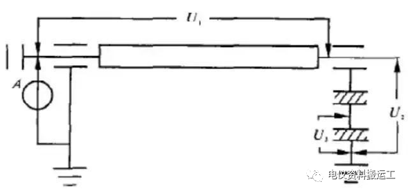
U1: Voltage difference between the two ends of the generator rotor shaft. Under normal circumstances, this is mainly caused by rotor magnetic asymmetry. Manufacturers usually provide empirical data; it is recommended to measure this after each minor overhaul and compare it with historical data.
U2: Voltage of the generator's rear shaft to ground.
U3: Voltage of the metal plate between the insulation layers of the generator's rear bearing to ground.
A: Current measured on the grounding lead of the generator's front-end grounding carbon brush.
U2, U3, and A should be measured periodically during operation. Changes in these data can indicate the generator's condition:
① U1 should be within the range provided by the manufacturer and should not change significantly compared to historical data. Otherwise, the condition of the generator's stator and rotor should be checked to determine the cause.
② U2 ≈ U3 (normal value). If U2 is greater than U3 (normal value), the grounding of the shaft grounding carbon brush needs to be checked. During operation, a short-term external grounding wire can be connected to the front shaft for grounding, and then U2 can be measured and compared.
③ U3 should be close to U2. Since the difference between U2 and U3 represents the voltage applied to the bearing oil film, excessive voltage may cause oil film breakdown. It is recommended that this difference not exceed 4V, or that U3 not be less than 70% of U2. Otherwise, the condition of the bearing's insulation to ground should be checked, such as surface contamination or insulation aging.
④ Generally, the current A flowing through the shaft grounding carbon brush ranges from a few milliamps to several hundred milliamps. If this value increases significantly, the bearing insulation should be checked in conjunction with the shaft voltage measurement.

Get in Touch
Related Products
")
")
")
")
")
")
")
")
")
Explosion-proof Motor Co., Ltd.
-
 cai@pinxingmotor.com
-
 +86-21-57566731
-
 +86-21-57566967
-
 No.699, Pinxing Rd., Qinggang Industrial Zone, Fengxian District, Shanghai, China.(East Gate)
-
No. 168, Qingling Rd, Qinggang Industrial Zone, Qingcun Town, Fengxian District, Shanghai, China (South Gate)
Copyright@ 2024 Shanghai Pinxing Explosion-proof Motor Co., Ltd. All Rights Reserved.
Privacy