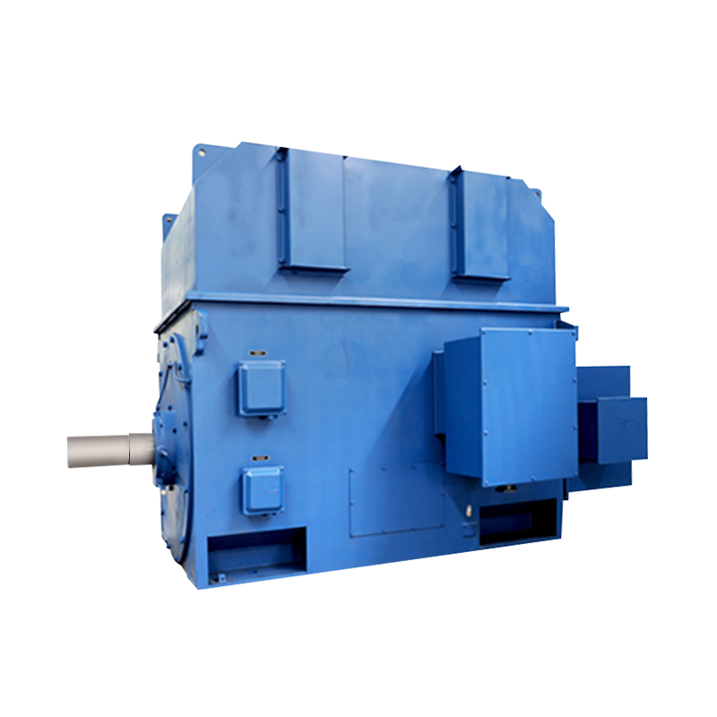
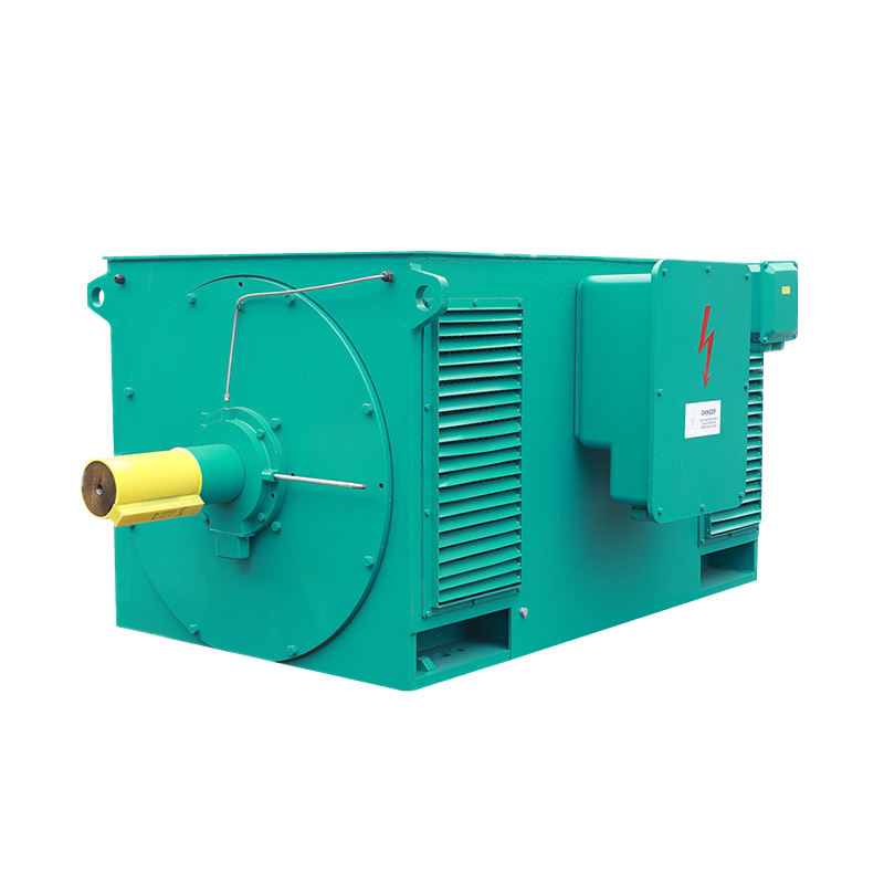
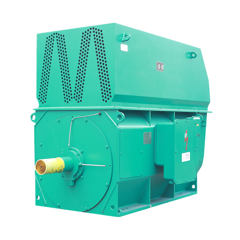
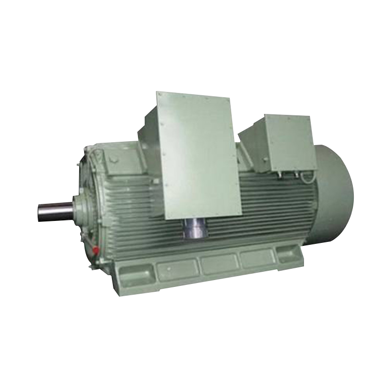
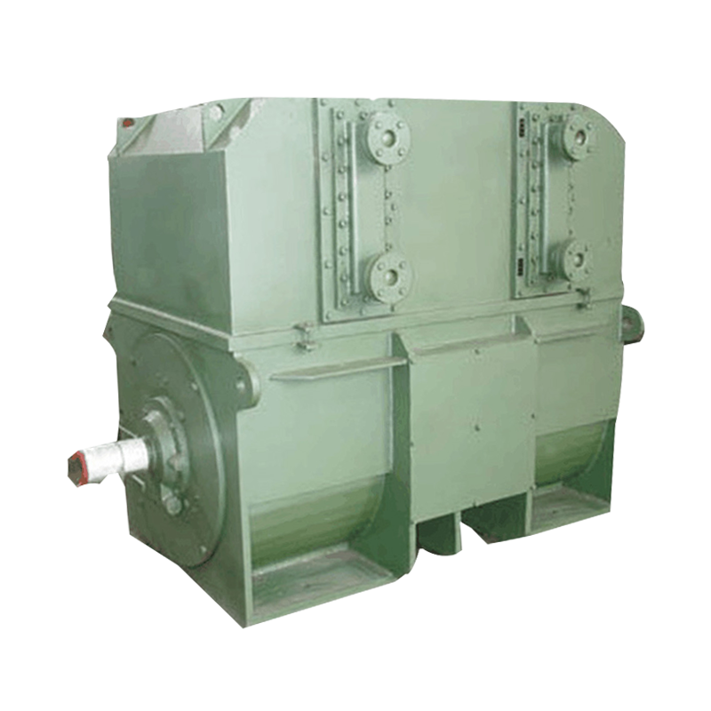
TAW THREE-PHASE SYNCHRONOUS INDUCTION MOTOR: A Key Technology Selection Guide for Enhancing Industrial Efficiency
Introduction: The Cornerstone of Efficient Industrial Power
In the world of industrial manufacturing and heavy machinery, the quest for reliable, efficient, and robust power is paramount. At the heart of countless applications—from driving pumps and compressors to operating conveyors and mills—lies the three-phase motor, an indispensable workhorse of modern industry.
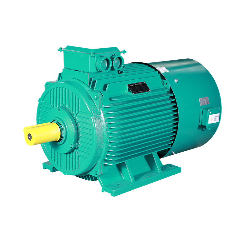
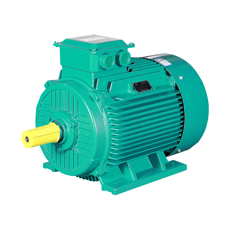
Among the various motor technologies available, the three-phase synchronous induction motor represents a significant advancement, merging the beneficial characteristics of both induction and synchronous machines. This motor type is engineered to deliver superior performance where efficiency and operational stability are critical. It achieves high efficiency during synchronous operation and provides robust starting torque without the need for complex initial synchronization.
This article serves as a comprehensive guide to understanding the three-phase synchronous induction motor. We will delve into its operational principles, key advantages, and essential selection criteria to demonstrate why it is considered a cornerstone technology for enhancing productivity and reducing operational costs in demanding industrial environments.
Chapter 1: Principle and Advantages: Why is the Synchronous Induction Motor an Efficient Choice?
The three-phase synchronous induction motor stands out in the industrial landscape due to its unique operational principle, which ingeniously combines the best attributes of two classic motor types. Understanding this hybrid mechanism is key to appreciating its significant advantages in efficiency and performance.
A Hybrid Operational Principle
The operation of this motor can be divided into two distinct phases:
- Asynchronous Start: Like a standard squirrel-cage induction motor, it starts by leveraging the principle of electromagnetic induction. When three-phase AC power is applied to the stator windings, a rotating magnetic field is created. This field induces currents in the rotor's squirrel-cage winding, generating torque that brings the rotor from standstill up to a speed close to synchronous speed. This design allows for robust and simple starting, often supporting direct-on-line (DOL) starting if the power grid permits.
- Synchronous Run: Once the rotor reaches approximately 95-97% of the synchronous speed, a direct current (DC) excitation supply is automatically applied to the rotor's field winding, typically via a static excitation system like a silicon-controlled rectifier (SCR) assembly. This DC excitation "locks" the rotor poles into step with the rotating magnetic field of the stator, pulling the rotor into precise synchronous speed. From this point onward, the motor runs as a true synchronous machine.
Core Advantages for Superior Efficiency
This dual-mode operation translates into several compelling advantages:
- High Power Factor and Efficiency: Once synchronized, the motor operates at a constant synchronous speed, independent of load variations. A key benefit is the ability to control its power factor by adjusting the DC excitation current. It can be operated at a unity power factor or even a leading power factor, effectively compensating for reactive power in the plant and improving the overall efficiency of the electrical system. This leads to reduced energy costs and lower demand on the power supply infrastructure.
- Excellent Starting Performance: The motor combines the high starting torque of an induction motor with the stable, efficient running of a synchronous motor. Its ability to withstand full-voltage starting makes it suitable for applications with robust electrical networks. Furthermore, its inherent design can contribute to a lower starting current compared to some alternatives, minimizing voltage dips during startup.
In summary, the three-phase synchronous induction motor offers a powerful solution by resolving the traditional trade-off between easy starting and efficient running. Its ability to provide high efficiency, controllable power factor, and reliable torque makes it an exceptionally efficient choice for continuous, heavy-duty industrial applications.
Chapter 2: Key Selection Factors: How to Configure the Right Motor for Your Application
Selecting the appropriate three-phase synchronous induction motor is crucial for ensuring optimal performance, longevity, and return on investment. Proper configuration goes beyond just power rating and requires careful consideration of several key technical parameters based on your specific application and site conditions.
1. Power Rating and Speed
The foundation of motor selection lies in defining two fundamental parameters:
- Rated Power (kW or HP): This must be sized to adequately drive the connected load (e.g., a pump, compressor, or fan) under all expected operating conditions, including a safety margin to avoid overloading.
- Synchronous Speed (RPM): This is determined by the supply frequency and the number of motor poles (e.g., 1500 RPM at 50 Hz for a 4-pole motor). The required speed is dictated by the driven equipment.
2. Voltage and Frequency Customization
A significant advantage of these motors is their flexibility in electrical supply compatibility. They are not limited to a single standard.
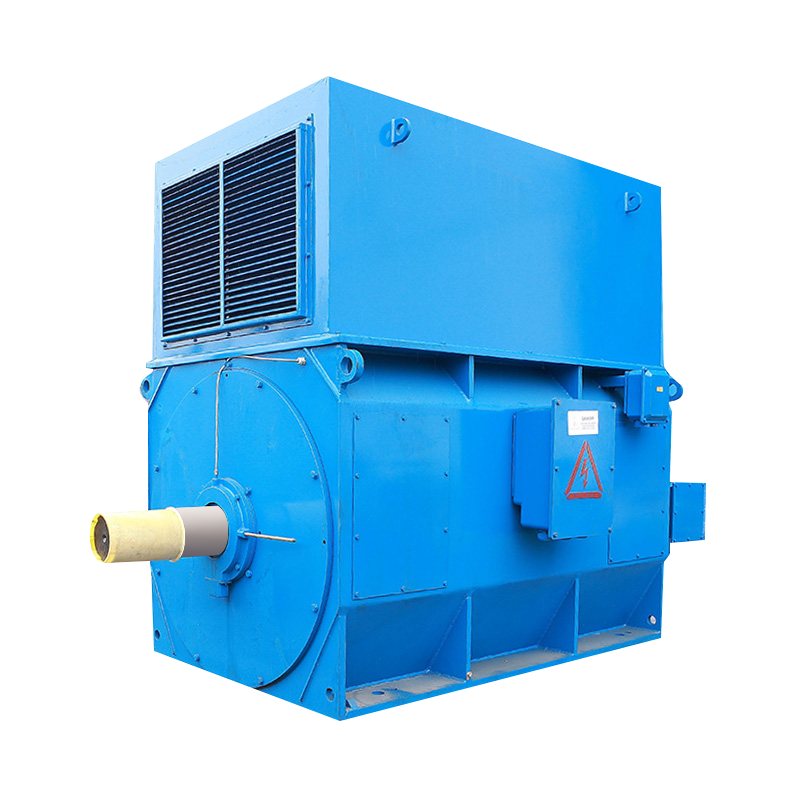
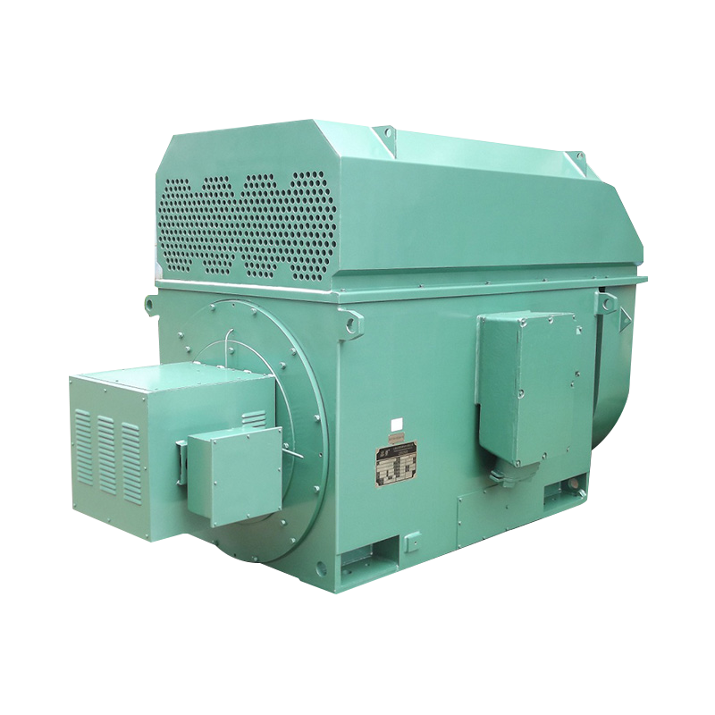
- Voltage: The motor can be manufactured to match various standard or non-standard grid voltages (e.g., 380V, 690V, 6kV, 10kV).
- Frequency: Designed for either 50 Hz or 60 Hz systems, which directly determines the base synchronous speed.
The table below outlines common voltage and speed combinations.
| Application Scale | Typical Rated Voltage | Supply Frequency | Synchronous Speed (4-pole) | Common Applications |
|---|---|---|---|---|
| Low Voltage | 380V / 400V / 690V | 50 Hz / 60 Hz | 1500 RPM / 1800 RPM | Pumps, fans, conveyors in general manufacturing |
| Medium/High Voltage | 3 kV / 6.6 kV / 10 kV / 11 kV | 50 Hz / 60 Hz | 1500 RPM / 1800 RPM | Large compressors, mining hoists, water supply pumps |
3. Specifying Rotation Direction
The standard design of a three-phase motor allows for bidirectional operation. It is critical to specify the required rotation direction (clockwise or counter-clockwise) when ordering, defined as viewed from the drive end (shaft extension side) of the motor. Manufacturers can configure the internal wiring accordingly to deliver the motor as requested, ensuring it drives the equipment correctly upon installation.
4. Considerations for High-Voltage Applications
Selecting a motor for high-voltage systems (e.g., 6kV and above) involves additional critical factors:
- Insulation System: The motor must feature a robust insulation system designed to withstand the higher electrical stresses, ensuring long-term reliability.
- Starting Method: While capable of direct-on-line starting, the high inrush current may be prohibitive on some networks. In such cases, reduced-voltage starting methods (e.g., auto-transformer, soft starter) must be considered alongside the motor selection.
- Protection and Control: High-voltage motors require coordinated protection systems (differential relays, overcurrent relays) and often more complex control gear for the excitation system.
By meticulously defining these parameters—Power, Speed, Voltage, Frequency, Rotation Direction, and application-specific nuances—you can ensure that the motor you select is perfectly tailored to your operational needs, delivering maximum efficiency and reliability.
Chapter 3: Modern Drives and Control: The Perfect Integration with Variable Frequency Drive Technology
The evolution of industrial automation has made speed control a critical requirement for optimizing processes and achieving significant energy savings. The three-phase synchronous induction motor, when paired with a Variable Frequency Drive (VFD), forms a highly efficient and controllable system that extends its advantages far beyond fixed-speed applications.
The Synergy of Synchronous Operation and Variable Speed
A VFD controls motor speed by varying the frequency and voltage of the power supplied to the stator. This capability transforms the motor from a fixed-speed asset into a precise and flexible component of your process control system.
The integration is particularly effective for the following reasons:
- Synchronization Across a Speed Range: The motor's inherent design allows it to maintain synchronous operation even as the frequency (and thus the synchronous speed) is changed by the VFD. The excitation system ensures the rotor stays locked to the stator's rotating field across a wide operating range, providing stable performance at any commanded speed.
- Controlled Torque and Power: VFDs allow for custom acceleration and deceleration ramps, reducing mechanical stress on both the motor and the driven equipment. Furthermore, control modes like Volts/Hertz (V/f) or sensorless vector control can be optimized to deliver the required torque characteristics for the application.
- Enhanced Excitation Control: In this setup, the DC excitation supply for the rotor is typically provided by the motor's own static exciter, which is powered by the output from the VFD. Modern excitation systems are designed to automatically adjust the field current to maintain optimal power factor and stability throughout the speed range.
Application Benefits: Fixed Speed vs. Variable Speed Drive
The decision between a fixed-speed and a VFD-controlled system depends heavily on the application requirements. The following table contrasts the two operational modes.
| Feature | Fixed Speed Operation (Direct-to-Line) | Variable Speed Operation (with VFD) |
|---|---|---|
| Speed Control | Fixed at synchronous speed (e.g., 1500 RPM). | Precisely adjustable across a wide range (e.g., 300-1500 RPM). |
| Starting Current | High inrush current (typically 5-7 times full load current). | Very low starting current (can be limited to less than full load current). |
| Energy Efficiency | High efficiency at full load and rated speed. | Extremely high efficiency at reduced speeds, ideal for centrifugal loads (pumps, fans) where power consumption reduces with the cube of speed. |
| Process Control | Simple on/off control. Limited process adjustment. | Precise process control (e.g., maintaining pressure, flow, or tension). |
| System Cost | Lower initial hardware cost. | Higher initial investment due to VFD cost, but often rapid ROI through energy savings. |
| Ideal Applications | Constant speed applications like compressors, constant-speed pumps, conveyors. | Applications requiring speed variation, soft starting, and precise control, such as fan systems, variable-flow pumps, and extruders. |
In conclusion, the integration of a three-phase synchronous induction motor with a VFD unlocks its full potential as a modern, intelligent, and highly efficient drive solution. This combination provides unparalleled control, maximizes energy savings, and protects mechanical systems, making it the preferred choice for a wide range of variable-speed industrial applications.
Chapter 4: Solving Industrial Pain Points: Addressing Specific Challenges
Industrial operations frequently encounter specific challenges related to power quality, mechanical reliability, and operational costs. The three-phase synchronous induction motor is engineered to provide effective solutions to some of the most common and critical issues.
Pain Point 1: Limited Grid Capacity and High Starting Current
The Challenge: Starting high-inertia loads can place a significant strain on the electrical distribution system. The high inrush current (or starting current) of a large motor can cause voltage dips, which may lead to malfunctions in other sensitive equipment connected to the same grid or even trip protective devices, halting production.
The Solution: The design of the three-phase synchronous induction motor offers inherent advantages in managing starting current.
- Inherent Starting Characteristics: While capable of direct-on-line (DOL) starting on robust grids, its starting current is typically lower than that of a standard NEMA Design B induction motor of equivalent power. This results in a reduced impact on the power system during the acceleration phase.
- Flexible Starting Methods: If the network is particularly weak, the motor is fully compatible with various reduced-voltage starting methods (e.g., auto-transformer, soft-starter). It is crucial to remember that with any reduced-voltage start, the starting torque is reduced by the square of the voltage reduction. The following table compares common starting methods.
| Starting Method | Starting Current (Relative to DOL) | Starting Torque (Relative to DOL) | Suitability for Synchronous Induction Motors |
|---|---|---|---|
| Direct-On-Line (DOL) | 100% (Reference) | 100% (Reference) | Excellent, when grid capacity allows. |
| Auto-Transformer | Reduced (e.g., 50-80% of DOL current) | Reduced proportionally to the square of the voltage. | Very Good, provides high torque per ampere of line current. |
| Electronic Soft-Starter | Precisely adjustable and limited (e.g., 200-300% of FLC) | Reduced and controllable. | Excellent, allows for smooth, controlled acceleration. |
| Variable Frequency Drive (VFD) | Very low (can be limited to <150% of Full Load Current) | High torque available even at low speeds. | Ideal, provides the best overall control and lowest grid impact. |
Pain Point 2: Poor Power Factor and Utility Penalties
The Challenge: Many industrial facilities suffer from a lagging power factor due to the prevalence of standard induction motors and transformers. This results in inefficient use of electrical power, increased current on cables, and often substantial financial penalties from the utility company.
The Solution: This is where the synchronous induction motor delivers one of its most significant benefits. Once synchronized, it can operate at a unity (1.0) or even a leading power factor. This capability allows it to act as a power factor corrector for the entire plant, improving the overall system efficiency and eliminating power factor penalties.
Critical Installation Reminder: Shaft Loading
A fundamental rule that must be strictly observed to ensure motor longevity is that the shaft extension must not be subjected to external radial or axial forces. Pulleys, couplings, or gears must be properly aligned and mounted to transmit only pure torque. Any external force can cause premature bearing failure, shaft damage, and catastrophic motor breakdown. Proper installation is non-negotiable for reliable operation.
By directly addressing these critical industrial challenges—grid limitations, power factor penalties, and mechanical reliability—the three-phase synchronous induction motor proves to be not just a source of power, but a strategic asset for enhancing overall plant performance and profitability.
Conclusion: Investing in Efficient Power to Empower the Industrial Future
In an increasingly competitive industrial landscape, the pursuit of operational excellence is no longer optional. The decisions made today regarding core infrastructure, such as motor-driven systems, have long-lasting implications for productivity, sustainability, and profitability. The three-phase synchronous induction motor emerges from our analysis not merely as a component, but as a strategic investment in a more efficient and reliable future.
This motor technology successfully bridges a critical gap in industrial power systems by combining the robust, simple starting of an induction motor with the exceptional running efficiency and power factor control of a synchronous machine. As we have explored, its benefits are direct and substantial:
- Tangible Cost Savings: Through high operational efficiency and the ability to correct plant-wide power factor, it directly reduces energy consumption and eliminates utility penalties.
- Enhanced System Reliability: Its stable synchronous operation and flexibility in starting methods protect both the electrical grid and the mechanical load, minimizing disruptive downtime.
- Operational Flexibility: Whether applied in fixed-speed duties or integrated with modern VFDs for precise process control, it delivers optimized performance across a vast range of applications.
The following table summarizes the key value propositions this technology brings to various industrial stakeholders:
| Stakeholder | Key Value Proposition |
|---|---|
| Plant Manager / Operator | Increased system reliability, reduced downtime, simplified compliance with operational demands, and superior process control. |
| Energy Manager | Significant reduction in active energy (kWh) costs and the elimination of reactive power (kVAR) penalties, leading to a lower total cost of electricity. |
| Maintenance Engineer | Robust construction, manageable starting characteristics that reduce stress on equipment, and clear installation guidelines for long-term reliability. |
| Financial Decision-Maker | Strong return on investment (ROI) through energy savings, increased productivity, and avoidance of downtime costs, justifying the capital expenditure. |
Choosing the right motor technology is a decisive step toward building a more resilient and profitable operation. By selecting the three-phase synchronous induction motor, industries are making a forward-thinking investment that pays dividends not only in reduced operational costs but also in empowered, future-ready manufacturing capabilities. It is a cornerstone technology for powering the intelligent, efficient industrial facilities of tomorrow.
Frequently Asked Questions (FAQ)
Q1: What are the main advantages of a synchronous induction motor compared to a standard high-voltage asynchronous motor?
A: The primary advantages lie in efficiency and power factor control. While both motors can handle heavy-duty applications, the synchronous induction motor operates at a constant synchronous speed, delivering higher efficiency, especially under partial loads. Its most significant benefit is the ability to operate at a unity or leading power factor. This corrects the plant's overall power factor, reducing energy waste and avoiding utility penalties, which a standard asynchronous motor cannot do. Shanghai Pinxing specializes in the engineering and manufacturing of these high-efficiency synchronous induction motors, providing clients with solutions for long-term energy savings.
Q2: Our application requires slow-speed, high-torque starting for a large compressor. Is this motor suitable, and what starting method do you recommend?
A: Yes, the three-phase synchronous induction motor is an excellent choice for high-torque applications like compressors. Its design provides high starting torque similar to an induction motor. For slow-speed, controlled starting to minimize grid impact, we highly recommend using a Variable Frequency Drive (VFD). A VFD provides the smoothest acceleration, limits starting current to a very low level, and provides full torque control. Shanghai Pinxing, as a AAA manufacturer of electrical equipment, produces a wide range of motors, including frequency conversion synchronous motors, that are perfectly compatible with VFDs. Our engineering team can help you select the optimal motor-and-drive combination for your compressor.
Q3: Can you provide motors for hazardous environments, such as coal mining or chemical plants?
A: Absolutely. A key strength of Shanghai Pinxing is our specialization in explosion-proof motor technology. We are a leading manufacturer of large and medium-sized high-voltage flameproof and increased safety explosion-proof motors, as well as low-voltage explosion-proof motors. Our products are engineered to meet the strictest safety standards for use in hazardous areas where flammable gases, vapors, or dusts are present. With our products exported to over 40 countries and widely used in coal mining, petroleum, chemical, and other critical industries, we have the proven expertise to deliver safe and reliable motor solutions for the most demanding environments.


 English
 русский
 Français
 عربى
عربى
