- 中文网站请点击 http://www.pinxinggroup.com
-
 +86-21-57566731
-
 cai@pinxingmotor.com
-
 DOWNLOAD


 English
 русский
 Français
 عربى
عربى
How to Wire a 3-Phase Electric Motor: Complete Star and Delta Wiring Guide
Content
- 1 Read the Nameplate Before Wiring a 3-Phase Electric Motor
- 2 Star vs Delta Wiring for a 3-Phase Electric Motor
- 3 Identify the Leads of a 3-Phase Electric Motor
- 4 Size Conductors for a 3-Phase Electric Motor
- 5 Motor Protection for a 3-Phase Installation
- 6 Pre-Energization Checks for a 3-Phase Motor
- 7 Frequently Asked Questions
Wiring a 3-phase electric motor is a routine industrial task, but one wrong connection can destroy a motor in under ten seconds. The most common cause of burned windings is not a faulty motor; it is a technician who connected the wrong configuration after misreading the nameplate. The correct procedure follows a fixed sequence: verify the nameplate voltage and current, choose Star or Delta wiring, identify the terminal leads, size conductors at 125% of the full-load current, and install an overload relay before power is ever applied. This guide covers that sequence in practical terms, using IEC and NEC rules where they matter most.
Read the Nameplate Before Wiring a 3-Phase Electric Motor
Every wiring decision starts with the nameplate data: rated voltage, frequency, full-load current, and the connection diagram. On a dual-voltage motor, the plate shows two voltages with corresponding schematic symbols. For example, "Delta 230V / Star 400V" means the motor must be wired in Delta for a 230V supply and in Star for a 400V supply.
If you connect a 400V-wired motor to a 230V supply, it will draw excessive current and overheat. If you connect a 230V-wired motor to a 400V supply, the insulation will fail immediately.
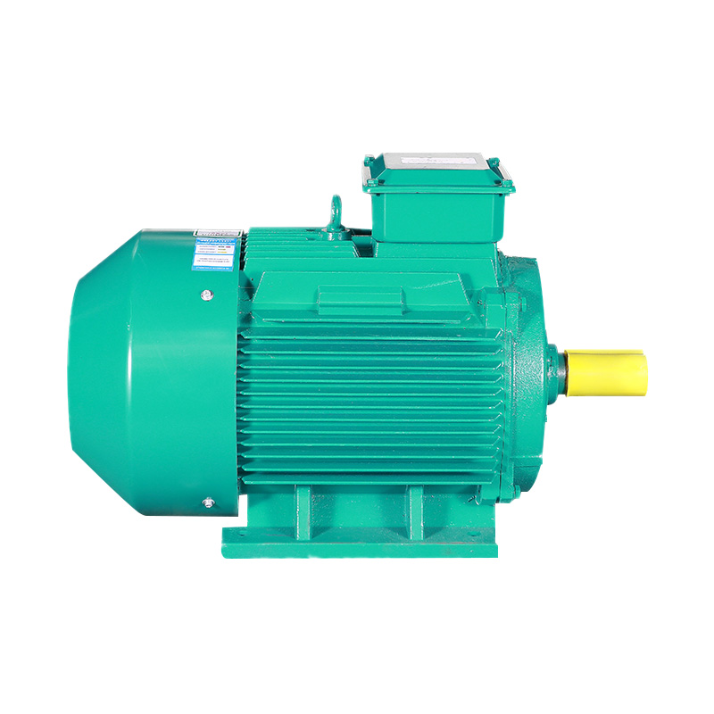 IE3 Series Three Phase Induction Motor for Reliable Nameplate RatingsThis IE3 motor series offers stable performance and clear nameplate data, helping you verify winding configurations and full-load current before installation.View Product →
The full-load current (FLA) listed on the nameplate is the starting point for conductor sizing and protection settings. It is not an average number; it is the rated current at the motor's rated output under full load. Shanghai Pinxing Explosion-proof Motor Co., Ltd. manufactures the YE3 series low-voltage standard industrial motors with nameplates that match the actual winding configuration and operating point, which reduces the risk of field misreading. A qualified manufacturer checks and records each winding set before dispatch, so the plate is a reliable reference during installation.
Star vs Delta Wiring for a 3-Phase Electric Motor
Star wiring connects the ends of all three winding sets at a common point, while Delta wiring connects each winding end to the start of the next. The practical difference is the voltage applied to each winding and the resulting starting torque. On a dual-voltage motor, Star is used for the higher voltage supply and Delta for the lower voltage supply. For a single-voltage motor, the nameplate determines the connection.
Star (Y) Wiring
- Each winding sees phase voltage equal to line voltage divided by 1.73
- Line current equals phase current
- Starting torque is roughly 33% of delta
- Used for 400V / 460V / 690V supplies
Delta (Delta) Wiring
- Each winding sees full line voltage
- Line current is 1.73 times phase current
- Starting torque reaches full rated value
- Used for 230V / 400V / 460V supplies
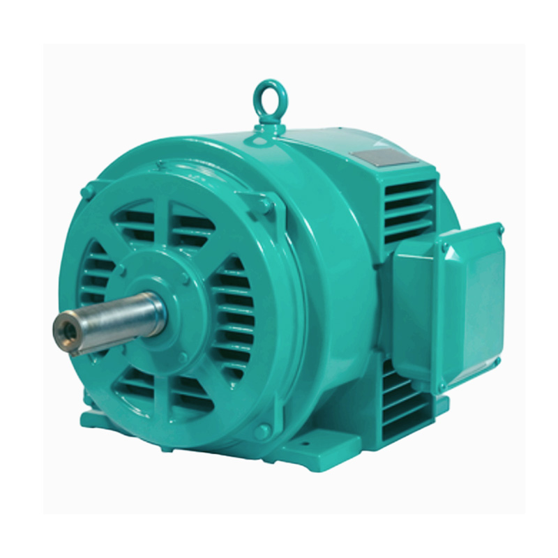 Custom Y Series Three-phase Asynchronous Motor with IP23 EnclosureSuitable for applications needing open drip-proof protection, this motor supports custom configurations and is built to match your specific voltage and wiring requirements.View Product →
For a single-voltage motor marked "400V Delta," wiring it in Star at 400V will starve each winding, and the motor will not develop rated torque. Wiring a "400V Star" motor in Delta at 400V applies 1.73 times the winding voltage across the insulation system and can destroy the motor almost instantly.
Identify the Leads of a 3-Phase Electric Motor
The terminal box configuration determines possible wiring options. A 9-lead motor is the most common dual-voltage machine, with terminal designations T1 through T9. Leads T1, T2, and T3 are the supply connections, T4, T5, and T6 are the winding mid-points, and T7, T8, and T9 are internal links. The connection diagram on the lid shows how to bridge terminals for high- or low-voltage operation.
| Supply Voltage | Configuration | Bridged Terminals | Supply Terminals |
| 230V low | Delta | None | T1, T2, T3 |
| 460V high | Star | T4-T5-T6 | T1, T2, T3 |
For 6-lead motors, there are three windings, each with two terminals, which can be connected in Star or Delta. 12-lead motors provide full access to all winding groups and are used where a star-delta starter is required. Learn more about how a three-phase squirrel-cage motor works to understand the winding theory behind these lead arrangements. Before connecting any wires, always verify the terminal letters on the box lid against the actual lead markings.
Size Conductors for a 3-Phase Electric Motor
Every branch-circuit conductor for a 3-phase motor must have an ampacity of at least 125% of the motor's full-load current, unless the circuit is covered by a special permission installation. This is the minimum requirement from NEC 430.22, and it is applied by electrical inspectors across North America and in many other regions through IEC adoption. The rule exists because motor starting inrush current can reach six to eight times full-load current, and conductor temperature rises quickly under repeated starts.
For long branch circuits, voltage drop is another limit. When cable length exceeds 30 meters, voltage drop may exceed 3%, reducing starting torque. In these cases, conductor size must be recalculated from the voltage-drop formula, not only from ampacity.
Motor Protection for a 3-Phase Installation
A breaker alone cannot protect a 3-phase motor from thermal overload. A standard molded-case breaker is designed to detect short circuits and ground faults, not slow current rises that do not reach the trip threshold. The overload relay, however, is a thermal or electronic device that continuously senses motor current. Its trip setting should be adjusted to the motor's nameplate FLA, typically between 100% and 115%, so the motor can deliver continuous rated output without nuisance tripping while still being shielded from sustained overload.
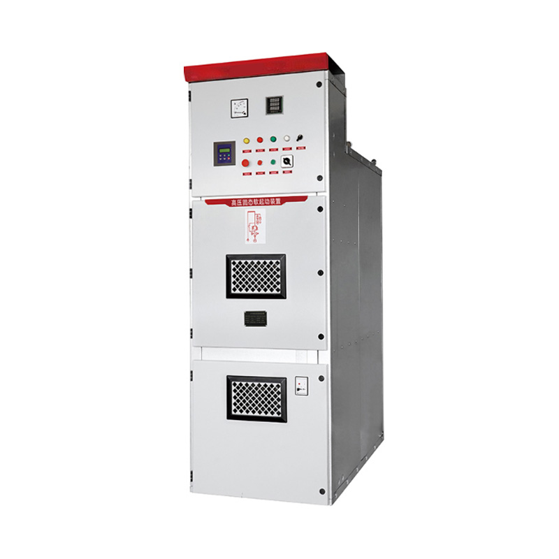 Custom Soft Starter for Smooth Motor Starting and ProtectionA soft starter reduces starting current and mechanical stress, complementing overload relays to safeguard motors on large-inertia loads.View Product →
For motors on large-inertia loads, soft starters reduce mechanical shock and grid disturbance. Install an overload relay in series with the soft starter, because the electronic protection parameters inside the starter may not cover the entire motor operating range.
The standard protection chain for a motor branch circuit is: short-circuit protection (fuse or breaker), then overload protection (overload relay), and then the motor itself. Never substitute the breaker for the overload relay, and never set the overload relay above 125% of FLA.
Pre-Energization Checks for a 3-Phase Motor
Before energizing a motor after rewiring, test winding insulation with a megohmmeter. A new or rebuilt motor should show insulation resistance above 1 megohm at 500V DC, and an older motor in good condition should exceed 100 megohms. If the reading is below 1 megohm, do not energize until the windings are dried or repaired.
- Disconnect all power and lock out the breaker before opening the terminal box.
- Verify the supply voltage with a multimeter at the motor terminals, not at the switchgear.
- Measure insulation resistance between each phase and ground; record the reading in the maintenance log.
- Check the phase sequence meter to confirm the motor will rotate in the required direction.
- Tighten all terminal bolts to the torque value marked on the terminal board; loose connections cause arcing.
Three-phase motor rotation is determined by phase sequence. To reverse the direction, swap any two supply conductors, for example L1 and L2. This is the same in IEC and NEC practice, and it does not affect the wiring of the motor itself.
Frequently Asked Questions
How do I know if my motor is wired for Star or Delta?
Check the nameplate and the terminal box lid. If the connection diagram shows the ends of all windings joined at a common point, it is Star. If it shows a closed triangle configuration, it is Delta. On a dual-voltage motor, the plate will list both configurations for the two supply voltages.
What happens if I wire a 3-phase motor incorrectly?
Wiring for the wrong voltage is the most damaging mistake. A Star-only motor connected in Delta sees 1.73 times rated voltage across each winding and fails almost immediately. A Delta-only motor connected in Star runs at only 58% of winding voltage, so it cannot reach rated speed, draws higher current, and trips the overload relay.
How do I reverse a 3-phase motor's rotation?
Swap any two of the three supply lines, for example L1 and L2. The motor's internal leads can stay untouched. Always perform the test without the load connected, and confirm with an ammeter that the motor is not drawing locked-rotor current.
Do I need an overload relay when using a VFD?
Most VFDs include internal overload protection functions, but many engineers still add a dedicated thermal overload relay for each motor in multi-motor or hazardous-duty installations. Check your local code. In explosion-proof or Ex-rated zones, the protection chain is stricter and usually requires external protection devices. For more practical examples of motor installations, see Pinxing's application cases.

Get in Touch
Related Products
 Shanghai Pinxing
Explosion-proof Motor Co., Ltd.
-
 cai@pinxingmotor.com
-
 +86-21-57566731
-
 +86-21-57566967
-
 No.699, Pinxing Rd., Qinggang Industrial Zone, Fengxian District, Shanghai, China.(East Gate)
-
No. 168, Qingling Rd, Qinggang Industrial Zone, Qingcun Town, Fengxian District, Shanghai, China (South Gate)
Copyright@ 2024 Shanghai Pinxing Explosion-proof Motor Co., Ltd. All Rights Reserved.
Privacy