- 中文网站请点击 http://www.pinxinggroup.com
-
 +86-21-57566731
-
 cai@pinxingmotor.com
-
 DOWNLOAD


 English
 русский
 Français
 عربى
عربى
What Is a 3 Phase Electric Motor? How It Works, Starts, and Gets Sized
Content
- 1 What a 3 Phase Electric Motor Is, in Plain Terms
- 2 How the Rotating Field Turns the Rotor: Slip, Torque and Rotor Types
- 3 Reading the Nameplate Before You Order a Replacement
- 4 How a 3 Phase Electric Motor Starts and What It Pulls from the Grid
- 5 Efficiency Classes: What IE3 and IE4 Change in Practice
- 6 Where a 3 Phase Electric Motor Fits, and Where It Does Not
- 7 Frequently Asked Questions About 3 Phase Electric Motors
A 3 phase electric motor is an AC motor whose stator carries three windings spaced 120 electrical degrees apart, so the magnetic field it creates rotates on its own, with no capacitor, no centrifugal switch and no auxiliary winding. That single design choice explains why nearly every industrial drive above roughly 0.75 kW runs on three phases: a 7.5 kW, 4-pole IE3 machine on a 400 V, 50 Hz supply draws about 14.6 A per phase, turns at roughly 1,450 rpm at full load, and delivers torque continuously through the electrical cycle instead of pulsing toward zero twice per revolution.
What a 3 Phase Electric Motor Is, in Plain Terms
A 3 phase electric motor is a rotating machine that converts three-phase electrical energy into mechanical energy using three stator windings and a rotor that is either induced or magnetically locked. Nothing external sequences those windings. The supply itself produces the rotation.
On a 50 Hz system each phase reaches its positive peak 6.67 milliseconds after the one before it. The three fields combine into one magnetic field that sweeps around the stator bore at synchronous speed, calculated as 120 times the supply frequency divided by the number of poles. Frequency and pole count set that speed, not motor size and not load.
A 3 phase electric motor is a machine in which three stator windings, driven by currents 120 degrees apart, generate a rotating magnetic field. That field turns at synchronous speed and drags the rotor along by electromagnetic induction or by magnetic locking.
| Poles | Speed at 50 Hz | Speed at 60 Hz | Typical duty |
| 2 | 3,000 rpm | 3,600 rpm | Centrifugal pumps, small high-head fans |
| 4 | 1,500 rpm | 1,800 rpm | The workhorse: pumps, conveyors, compressors, machine tools |
| 6 | 1,000 rpm | 1,200 rpm | Crushers, mixers, large process fans |
| 8 | 750 rpm | 900 rpm | Ball mills, extruders, slow screw conveyors |
Pole count also shifts frame size and torque per ampere. An 8-pole motor of the same power makes more torque at lower speed, so it is larger, heavier and more expensive than a 4-pole unit of equal rating. That trade-off drives most selection decisions long before efficiency class enters the discussion.
How the Rotating Field Turns the Rotor: Slip, Torque and Rotor Types
The rotor turns because the rotating stator field induces current in the rotor conductors, and the force between that current and the field produces torque. The rotor can never quite catch the field, and the speed difference between the two is called slip.
Slip is expressed as a percentage of synchronous speed. A 4-pole motor on 50 Hz has a field speed of 1,500 rpm; if it runs at 1,455 rpm under load, slip is 3 percent. Standard industrial motors sit between 1 and 5 percent at full load, with large machines at the low end and small ones at the high end. Slip is also what makes an induction motor self-regulating: add load, the rotor slows a little, more flux cuts the rotor conductors, and torque climbs until the two balance again.
Squirrel cage rotor
Conductive bars shorted by end rings, with no brushes and no external resistance. Lowest cost, highest reliability, and the default choice for pumps, fans, compressors, conveyors and most machine tools. Starting current is high, typically 6 to 8 times full-load current.
Wound rotor with slip rings
A three-phase winding on the rotor is brought out through slip rings so external resistance can be inserted during the start. That raises starting torque while cutting starting current, which matters for high-inertia loads such as mills, hoists and crushers. The price is brush and ring maintenance.
If you want the mechanics in more depth, how a squirrel cage motor builds torque walks through the current paths step by step.
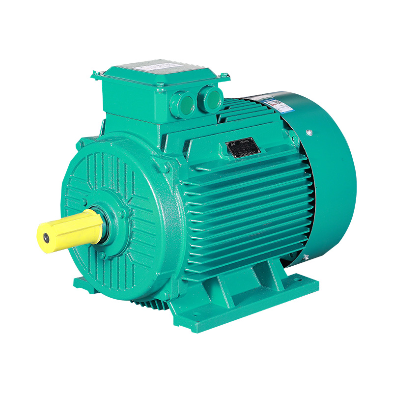 IE4 Series Three-Phase High Efficiency Induction MotorFor readers comparing replacement motors, this IE4 series covers H80–355 mm frames and common industrial fan, pump, and compressor duties.View Product →
Reading the Nameplate Before You Order a Replacement
Every value needed to match a replacement motor is stamped on the nameplate, and skipping one of them is the most common reason a technically correct motor fails in service within a few months.
| Field | What it tells you | Typical entry |
| Voltage and connection | Line voltage and how the six leads are linked | 400 V delta, 690 V star |
| Frequency and poles | Basis of the synchronous speed | 50 Hz, 4 pole |
| Rated current | Sizing for cable, contactor and overload relay | 14.6 A |
| Power factor | How the supply sees the load | 0.84 |
| Duty | Whether the load is continuous or cyclic | S1 continuous |
| Insulation class | Thermal headroom above the rated rise | Class F, class B rise |
| Enclosure | Dust and water protection | IP55 |
| Efficiency class | Minimum efficiency tier under IEC 60034-30-1 | IE3 |
| Frame and mounting | Shaft height and fixing pattern | 132 frame, IM B3 |
When the plate is illegible, three measurements settle most of it:
- Measure shaft diameter and the distance between fixing holes to identify the frame size.
- Count the supply conductors, because a three-phase motor has three line leads plus earth and no capacitor.
- Read current with a clamp meter at a known load and compare it with the expected value for that rating.
How a 3 Phase Electric Motor Starts and What It Pulls from the Grid
Started direct-on-line, a three-phase induction motor draws 6 to 8 times its full-load current until it reaches speed. That surge, not the running current, usually decides cable size, protection settings and the starting method.
At standstill the rotor behaves like a short-circuited transformer secondary, so the impedance limiting current is very low. As speed rises, slip falls, rotor frequency falls, and current drops back toward the nameplate value.
| Method | Starting current | Starting torque | Where it fits |
| Direct-on-line | 6 to 8 times full load | 150 to 200 percent of rated | Small motors on a stiff supply with loads that tolerate a hard start |
| Star-delta | About one third of direct-on-line | About one third of direct-on-line | Fans and pumps that reach speed quickly, never high-inertia loads |
| Soft starter | 2 to 4 times full load | Adjustable ramp | Conveyors and pumps where mechanical shock must be limited |
| Variable frequency drive | 100 to 150 percent of full load | Rated torque from zero speed | Speed control plus the gentlest possible start |
A variable frequency drive cuts starting current to roughly 100 to 150 percent of full-load current and delivers full torque from zero speed. That duty is harder on insulation and cooling than a fixed-speed start, so inverter-fed applications belong on a motor built for it rather than on a standard frame with a drive bolted on.
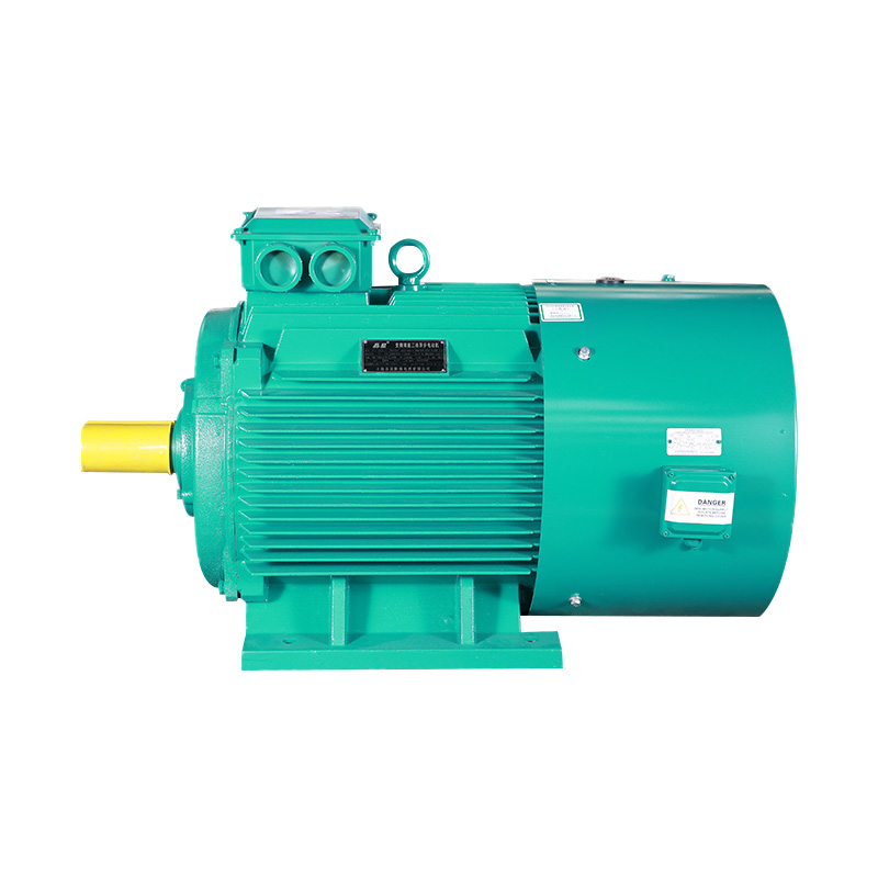 YPT Series Three-Phase Variable-Frequency Induction MotorBuilt for inverter-fed industrial drives, this YPT series offers H80-355 mm frames, IC416 or IC411 cooling, and 5-100 Hz operation.View Product →
Efficiency Classes: What IE3 and IE4 Change in Practice
IE3 and IE4 are minimum-efficiency tiers defined by IEC 60034-30-1, and the gap between them looks small in percentage terms until the motor runs thousands of hours a year.
For a 7.5 kW motor, moving from IE3 to IE4 cuts input power from about 8.30 kW to about 8.12 kW, a saving of roughly 0.18 kW. Over 4,000 running hours that is about 720 kWh a year, which normally repays the price premium within two to four years where electricity costs more than 0.10 USD per kWh. Above a few hundred kilowatts the calculation changes character, because the drive moves to medium voltage and the design constraints shift toward insulation, cooling and starting current. High voltage machines in the Y, YKK, YR and YKS families exist precisely for that band, and their selection data is published in the high voltage motor catalog.
Where a 3 Phase Electric Motor Fits, and Where It Does Not
Three-phase motors cover almost every industrial load above roughly 0.75 kW, and single-phase designs stay common only below that or where no three-phase supply exists.
Typical duty includes pumps, fans, compressors, conveyors, mixers, crushers and machine tool spindles across mining, metallurgy, cement, petroleum, chemical, power, water treatment and marine plants. In hazardous areas the same three-phase design has to be built to a certified protection concept, either flameproof Ex d with controlled flame paths or increased safety Ex e with reinforced insulation and terminal clearances. Shanghai Pinxing Explosion-proof Motor Co., Ltd., based in Shanghai, produces YBX3 and YBX4 low-voltage explosion-proof motors alongside high voltage flameproof ranges for coal, petrochemical and marine service, with exports to more than 40 countries.
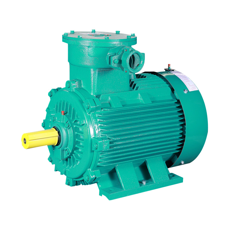 YBX4 Series Low Voltage Explosion-Proof MotorFor hazardous areas, this flameproof motor covers H80-355 mm frames and 0.75-355 kW, with IP55 protection for pumps, fans, compressors, crushers.View Product →
The real limits of the technology are worth stating plainly:
- A three-phase motor cannot run from a single-phase supply without a phase converter or a drive rated for single-phase input, and it must be derated when it does.
- Speed is fixed by frequency and pole count unless a drive or a two-speed winding is added.
- Inverter duty adds voltage stress on the winding, so a standard motor may need inverter-grade insulation.
Reviewing application case studies from comparable industries is a fast way to confirm a frame size and protection level before a purchase order is raised.
Frequently Asked Questions About 3 Phase Electric Motors
Can a 3 phase electric motor run on a single-phase supply?
Not directly. A static or rotary phase converter, or a drive with single-phase input, can run it, but the motor must be derated because the third leg is synthesised rather than supplied. Expect usable output of roughly 50 to 60 percent of nameplate power on a static converter, and check the drive manual before ordering.
What is the difference between a 2 pole and a 4 pole 3 phase motor?
Pole count sets synchronous speed: 3,000 rpm at 50 Hz for two poles against 1,500 rpm for four. A 2-pole motor of the same power is smaller and cheaper but produces less torque and spins faster, so it suits pumps and fans. The 4-pole design dominates general industrial duty for exactly that balance.
How can I tell whether a motor is three phase?
Look at the leads and the nameplate. A three-phase motor has three line conductors plus earth and no capacitor, while a single-phase motor carries a capacitor and a start or run winding. The voltage entry usually settles it as well, since a three-phase industrial rating reads 400 V or 690 V rather than 230 V.
What does slip mean on a 3 phase electric motor?
Slip is the difference between synchronous speed and actual rotor speed, expressed as a percentage of synchronous speed. A 4-pole motor running at 1,450 rpm on a 50 Hz supply has about 3.3 percent slip at full load. A sudden rise well above 5 percent usually points to overload, a failing bearing or a winding problem.

Get in Touch
Related Products
 Shanghai Pinxing
Explosion-proof Motor Co., Ltd.
-
 cai@pinxingmotor.com
-
 +86-21-57566731
-
 +86-21-57566967
-
 No.699, Pinxing Rd., Qinggang Industrial Zone, Fengxian District, Shanghai, China.(East Gate)
-
No. 168, Qingling Rd, Qinggang Industrial Zone, Qingcun Town, Fengxian District, Shanghai, China (South Gate)
Copyright@ 2024 Shanghai Pinxing Explosion-proof Motor Co., Ltd. All Rights Reserved.
Privacy