- 中文网站请点击 http://www.pinxinggroup.com
-
 +86-21-57566731
-
 cai@pinxingmotor.com
-
 DOWNLOAD


 English
 русский
 Français
 عربى
عربى
Synchronous Motor Guide: Working Principle, Types, and Industrial Applications
Content
A plant engineer specifying a replacement driver for a large centrifugal compressor usually starts with the same question: how do I keep speed constant when load changes? The answer is a synchronous motor. Unlike an induction machine, which operates with slip so that speed drops as torque rises, a synchronous motor locks its rotor to the rotating magnetic field of the stator. At steady state, shaft speed equals synchronous speed, regardless of load, up to the pull-out torque limit. That single property — zero slip — is why synchronous motors remain the standard choice for large fans, pumps, compressors, and grinding mills across heavy industry.
How a synchronous motor works
The stator of a synchronous motor resembles that of a three-phase induction motor: a laminated iron core with a distributed three-phase winding. When the winding is connected to the supply, it produces a magnetic field that rotates around the air gap at a speed determined by the supply frequency and the number of poles: Ns = (120 × f) / P, where Ns is the synchronous speed in revolutions per minute, f is the supply frequency in hertz, and P is the number of magnetic poles.
The rotor carries field poles that are magnetised by direct current. Once the rotor is running near synchronous speed and the DC field is applied, the rotor poles lock onto the moving stator poles and the machine rotates as a single magnetic unit. From that point there is no slip. If the load increases, the rotor falls back by a small torque angle — normally a few electrical degrees — but speed stays exactly the same.
In practical terms, a four-pole motor on a 50 Hz network turns at exactly 1,500 rpm whether it drives a lightly loaded fan or a fully loaded compressor. The stability benefits of this behaviour are explained in more detail in our discussion of how a synchronous motor improves stability and ensures efficient operation.
| Number of poles | Speed at 50 Hz (rpm) | Speed at 60 Hz (rpm) |
|---|---|---|
| 2 | 3,000 | 3,600 |
| 4 | 1,500 | 1,800 |
| 6 | 1,000 | 1,200 |
| 8 | 750 | 900 |
| 10 | 600 | 720 |
| 12 | 500 | 600 |
Why a synchronous motor is not self-starting
Connect a synchronous motor directly to a fixed-frequency supply with the DC field applied, and nothing useful happens. With the rotor at standstill, the stator field sweeps past the rotor poles at supply frequency. The rotor sees alternating attraction and repulsion — at 50 Hz this reverses 100 times per second — so the average torque is zero. With no net starting torque, the rotor cannot accelerate.
This is the most common misunderstanding during first-time selection. It is not a fault in the machine; it is simply the physics of synchronism. Every industrial synchronous motor therefore needs a deliberate starting strategy. The three approaches used in practice are:
- Damper (amortisseur) winding. Copper or brass bars are embedded in the pole faces and short-circuited at both ends, forming a squirrel-cage structure. The motor starts as an induction motor, accelerates to roughly 95–98 percent of synchronous speed, and then the DC field is applied to pull the rotor into step.
- Variable frequency drive. The supply frequency is ramped from a low value up to rated speed, so the rotor follows the rotating field from standstill. This is preferred when the application also needs speed control or reduced inrush during starting.
- Pony motor. A small auxiliary motor accelerates the main rotor to near synchronous speed before the field is applied. This appears mainly on older, very large installations.
The DC field current comes from an excitation system. On large high-voltage machines the usual arrangement is a static excitation panel that feeds the rotor through slip rings, or a brushless exciter mounted on the shaft. The excitation system also regulates field current during normal operation, which is what allows power factor control. Because excitation faults are among the most common causes of synchronous motor trips, the synchronous motor excitation cabinet should be selected as carefully as the motor itself.
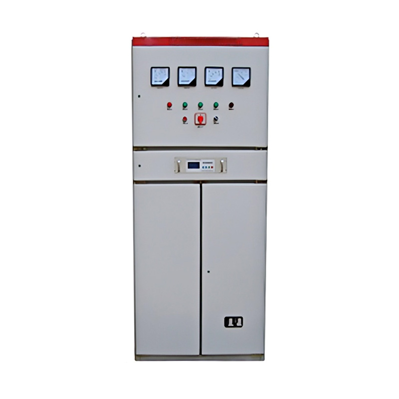 Custom Synchronous Motor Excitation Cabinet Suppliers, Manufacturers - ShanghaiShanghai Pinxing Explosion-proof Motor Co., Ltd is China Synchronous Motor Excitation Cabinet Suppliers and Synchronous Motor Excitatio...View Product →
Main types of synchronous motors
Non-excited synchronous motors
Not every synchronous motor needs a DC rotor field. Three variants use other means to keep rotor and stator field in step:
- Permanent-magnet synchronous motors use magnets on the rotor. They are compact and highly efficient, and they dominate servo drives, robotics, and precision motion control.
- Reluctance synchronous motors use the magnetic saliency of the rotor to synchronise. They are simple and robust, and they appear increasingly in efficiency-driven pump and fan applications.
- Hysteresis motors use a rotor of semi-hard magnetic material to produce very smooth, quiet torque, which suits timing and instrument drives.
Externally excited synchronous motors
These machines carry a wound rotor fed with DC through slip rings or a brushless exciter. Two rotor constructions dominate:
- Salient-pole rotors have projecting poles and suit low- and medium-speed duties — ball mills, crushers, reciprocating compressors, and hydro generators.
- Cylindrical rotors have a smooth distributed field winding and suit high-speed turbomachinery such as turbine-driven compressors.
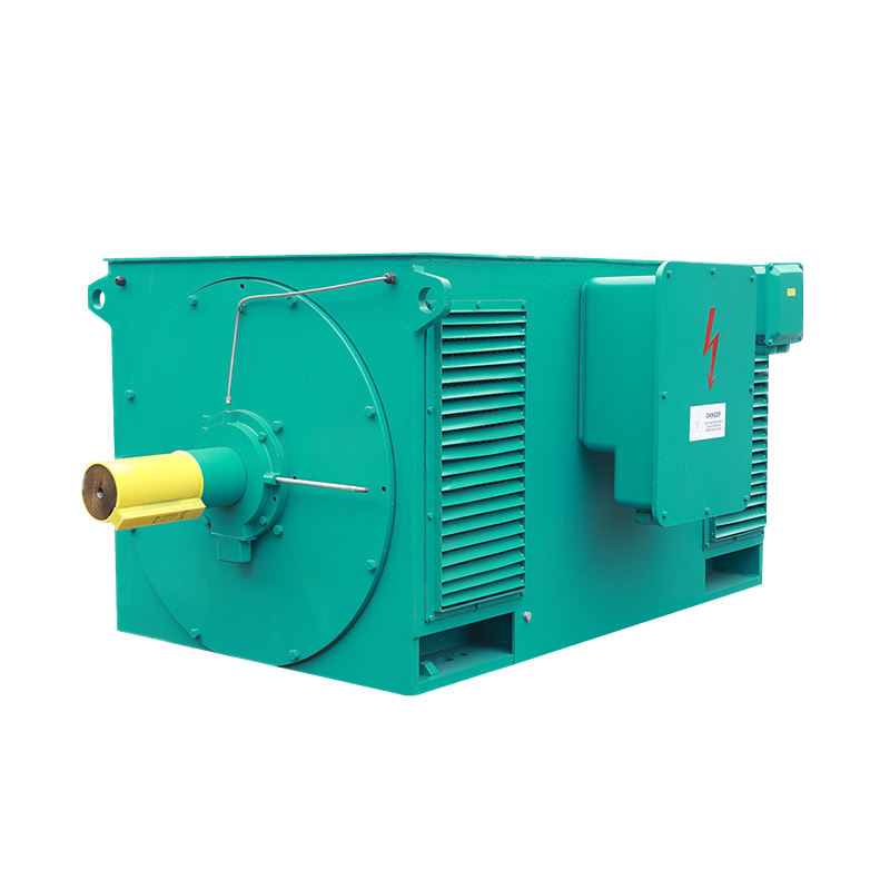
For high-voltage industrial service, externally excited machines cover the ratings where constant speed and power factor correction matter most. In our high-voltage motor range, the T, TK, and TM series high-voltage synchronous motors cover compressor, mill, and fan duties on 6 kV and 10 kV plant networks.
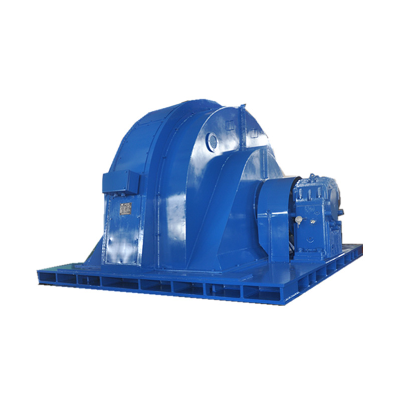 Wholesale T series three-Phase Synchronous Induction Motor Manufacturers, FactorShanghai Pinxing Explosion-proof Motor Co., Ltd is China Wholesale T series three-Phase Synchronous Induction Motor Manufacturers and T s...View Product →
Where high-voltage synchronous motors deliver the most value
The decision to install a synchronous motor is usually economic before it is technical. On large, continuously running loads, the machine offers four measurable advantages:
- Constant speed with zero slip — process flow, pressure, and product quality stay stable even as load varies.
- Power factor correction — by over-exciting the field, the motor draws leading reactive current and offsets lagging reactive power from induction motors elsewhere in the plant. In some plants, a single synchronous motor improves overall power factor enough to remove a utility penalty.
- Higher efficiency — at ratings of 500 kW and above, synchronous motors typically show lower total losses than equivalent induction motors.
- Larger air-gap tolerance — the rotor is mechanically robust and the air gap is larger than on an induction machine of similar rating, which simplifies maintenance.
Ball mills in mineral processing, gearless mill drives, crushers, blast-furnace blowers, large induced-draft fans, and high-pressure pumps are the classic applications. Because these loads run continuously at fixed speed, the higher first cost of the motor plus excitation system is recovered quickly through efficiency gains and power factor savings. Our review of the key advantages of high-voltage synchronous motors compares these savings in more detail.
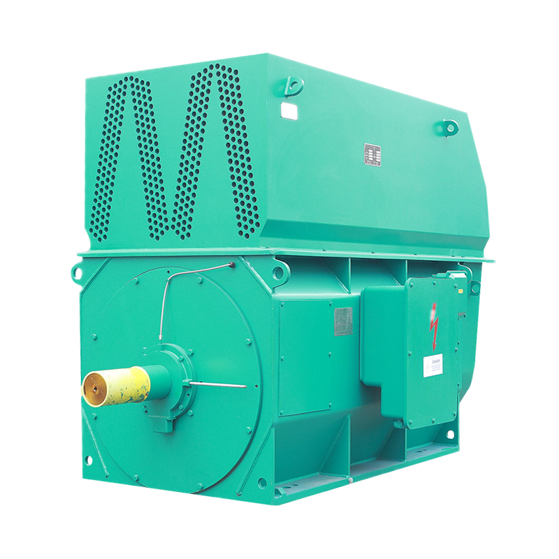
For fan and pump duties in power stations and water supply systems, the TAW series three-phase synchronous motors are a common medium-voltage choice, supported by the same excitation and control principles described above. In the special case where the mechanical load is removed, the same machine can run uncoupled as a synchronous condenser and supply reactive power to the plant network. We also publish practical guidance on why industrial users choose high-voltage synchronous motors when evaluating alternatives such as slip-ring induction motors.
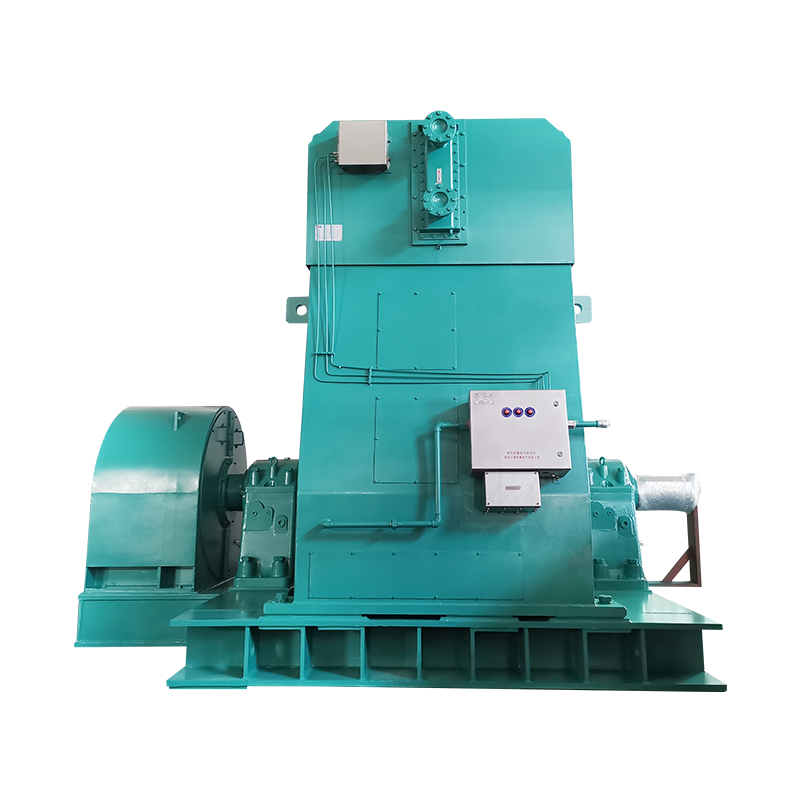 Wholesale TAW Three-Phase Synchronous Induction Motor Manufacturers, FactoryShanghai Pinxing Explosion-proof Motor Co., Ltd is China Wholesale TAW Three-Phase Synchronous Induction Motor Manufacturers and TAW Thre...View Product →
Synchronous motor selection checklist
Specifying a synchronous motor is a system exercise. The three most common procurement mistakes are underestimating starting requirements, treating the excitation system as an afterthought, and overlooking the enclosure specification. Work through the following checklist to avoid them:
- Load torque–speed profile. Confirm starting torque, pull-in torque, and pull-out torque margins against the driven load curve.
- Load inertia and starting time. With damper starting, the machine behaves as an induction motor during acceleration; verify that the damper winding stays within its thermal limit for the required starting time.
- Voltage and insulation. Match the motor to the plant bus — typical medium-voltage levels are 3.3 kV, 6 kV, 10 kV, and 11 kV — and confirm the insulation class and vacuum pressure impregnation (VPI) treatment for reliable long-term service.
- Enclosure and environment. In hazardous atmospheres, specify a certified explosion-proof synchronous motor; for clean indoor service, IP23 or IP54 enclosures normally suffice.
- Excitation and control. Decide between static excitation with slip rings and brushless excitation, and confirm that the excitation cabinet interfaces with existing protection relays and the plant control system.
- Power factor objective. State the required power factor — commonly 0.8 or 0.9 leading — so that the excitation design can deliver the reactive power compensation you expect.
None of this is theoretical. A synchronous motor that is correctly specified starts reliably, holds speed under load, corrects plant power factor, and runs for decades with routine maintenance. Get the starting method or excitation system wrong, and the same machine can trip on pull-out, overheat its damper bars, or oscillate under load. The engineering effort pays back quickly on large fixed-speed drives — which is exactly why the synchronous motor remains a core technology in high-voltage industrial power systems.

Get in Touch
Related Products
 Shanghai Pinxing
Explosion-proof Motor Co., Ltd.
-
 cai@pinxingmotor.com
-
 +86-21-57566731
-
 +86-21-57566967
-
 No.699, Pinxing Rd., Qinggang Industrial Zone, Fengxian District, Shanghai, China.(East Gate)
-
No. 168, Qingling Rd, Qinggang Industrial Zone, Qingcun Town, Fengxian District, Shanghai, China (South Gate)
Copyright@ 2024 Shanghai Pinxing Explosion-proof Motor Co., Ltd. All Rights Reserved.
Privacy